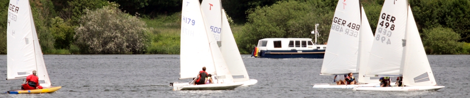
class regulations of the Tempo Scow
INDEX:
sail plan of the Tempo
- 1. general items
- 2. charges/licenses
- 3. manufacturer
- 4. measurement certificate
- 5. mearurement modalities
- 6. sail emblem
- 7. building procedure
- 8. measurement regulations
- 9. centreboard
- 10. rudder
- 11. weight
- 12. mast
- 13. main boom
- 14. spinnaker boom
- 15. standing and running rigging, leading of sheets
- 16. fittings
- 17. sails
- 18. racing equipment
- 19. yacht racing rules
- 20. plans of reference
1. GENERAL ITEMS
1.1
The TEMPO SCOW is a two hand one-type dinghy designed by Jack Köper.
1.2
The class regulations shall make sure that all boats of this class are as far as possible equal in all points which influence the safety, the speed and the sail qualities. The regulations have to be interpreted in this meaning.
1.3
Changes of the class regulations can be decided only with a 2/3 majority during the member meeting of the class organization. They should be coordinated with the DUTCH class organization before and the TECHNICAL TRASH of the Deutsche Segler-Verband has to be informed.
1.4
All boats of this class shall comply with the class regulations valid during the construction time.
The administration of the class is incumbent of the class organization in cooperation with the Deutsche Segler-Verband. The class oganization and the Deutsche Segler-Verband do not assume any legal liability with regard to this regulation and any claims derived from it.
1.5
These regulations are valid as of October 1st, 1994. Boats which were built before this appointment and do not comply with these regulations can receive a measuring certificate if these were adhered to the regulations valid in the time of construction.
2. CHARGES / LICENSES
2.1
The measurement and registering charges are fixed by the Deutsche Segler-Verband and vary according to the respectively valid scales of charges.
2.2
The license fees amount to EUR 20.00 and have to be paid to the class organization before receipt of the sail number.
The class organization passes this amount on to the heirs of the designer, Jack Köper.
3. MANUFACTURER
3.1
By his signature on the measuring certificate the manufacturer explains that the boat has been built in agreement with the valid regulations.
3.2
The manufacturer is obliged to remove all rule adversities, which are provable and arisen for the building, at the expense of his own.
4. MEASUREMENT CERTIFICATE
4.1
Only such boats may take part in active list races for which a valid measuring certificate is available which is franked by the Deutsche Segler-Verband and issued to the name of the owner.
4.2
The measuring certificate is prepared by the Deutsche Segler-Verband due to a measurement form issued by a recognized measurer.
4.3
With the measuring certificate the owner gets a measurement badge which has to be attached to the mirror of the boat considerably visibly. This badge indicates the boat as duly measured.
4.4
The measuring certificate becomes invalid through:
4.4.1 Owner change:
In this case the measuring certificate must be submitted to the Deutsche Segler-Verband together with an explanation of the buyer and the pre-owner that no changes which violate the class regulations were carried out at the boat.
4.4.2 Changes:
Changes which were carried out after the first measurement to hull, rigging or sail. To this a follow-up measurement by a recognized measurer is necessary.
5. MEASUREMENT MODALITIES
5.1
The measurement may be carried out only by a measurer appreciated by the Deutsche Segler-Verband.
5.2
No measurer may measure a boat, spars or equipment, which belong to him, which were produced by him or at which he is involved.
5.3
The measurement must be carried out with the official stencils which are authorized and approved by the Deutsche Segler-Verband.
5.4
After the first measurement the owner is responsible for the compliance with the class regulations.
5.5
The measurement of the TEMPO SCOW can be carried out in form of a type check at plastic series boats.
The conditions of a type check are regulated in detail between the class organization, the building shipyard or the builder. The check itself is carried out after the following scheme:
5.5.1
The first boats of a series (at least 3) are checked by a recognized measurer according to these class regulations.
5.5.2
The measuring sheets of the type check are checked by the Deutsche Segler-Verband and the type check is approved at sufficient building precision.
5.5.3
Furthermore the measurer checks irregularly the building shipyard.
5.5.4
The building shipyard obliges itself to adhere to the class regulations and to bear the costs for the follow-up measurement of the complete series at deviations stated later.
5.5.5
If the moulds are replaced or changed, the measurer must carry out the measurements demanded after 5.5.1 for this series once more.
5.5.6
Boats of a type check series receive a measuring certificate with the remark "type checked". An individual entry of all measures is dropped. However, weight and the parts, which are not delivered by the shipyard according to the standard of the type check and therefore are subject of an individual measurement, must be filled out.
6. SAIL EMBLEM
6.1
Nationality letters and sail number have to be good readably branded, written or hammered into the hull; sail number and the number tightly brought into the hull must be identical.
6.2
The size and the manner of the attachment of the nationality letters, the sail number and the sail emblem into main sails and spinnakers varies according to the respectively valid rules of the international yacht racing rules.
6.3
The sail emblem consists of a stylized "T", like one can get it from the reference plan no. 6.
7. BUILDING PROCESS
7.1 Dimensions
Every boat must agree with the data and measures summarized in the measurement form, formulated in these regulations.
7.2 Material
Coal and aramid fibres are forbidden for the hull, mast, boom, spinnaker boom and for all sails. New, untill now in this class unusual materials require the admittance by the TECHNICAL TRASH of the GERMAN as well as the DUTCH class organization or an admission to these regulations.
7.3 Design
The construction of the hull is free, unless the following restrictions:
7.3.1
On wooden boats, the deck must be at least 5 mm, the floor at least 7 mm in diameter.
7.3.2
Up to 4 self bailer can be attached in the cockpit ground or 2 flaps in the transom with a complete maximum pumping area of 29 sq cm, a minimal pumping area of 5 sq cm is specified. If flaps are appropriate in the transom, they must be connected to the cockpit by watertight tubes, which diameter must correspond to the maximum pumping area of the transom flaps (diameter at most 43 mm). The demands of regulation 7.3.3 must be adhered to.
The available leaving area (e.g. mobile flap) or the opening in the transom area is understood by the concept "pumping area".
7.3.3
The spaces under the side decks as well as in front of frame 1 (after body) and frame 5 (forebody) must be performed as buoyancy tanks. Openings in the buoyancy tanks must be locked waterproofly. Every tank must have at least an inspection hole. Every inspection hole must be safeguarded against unintentional opening and is permanently held unanimously as long as the boat is in a race. The inspection opening must show at least 85 mm in diameter.
7.3.4
Shape, location and measurements of the cockpit, the centreboard case, the centreboard slit and the mast step must correspond to the measures of the drawings. The connection of the cockpit lengthway bulkhead with the bottom has to lie within the limitations which are indicated in the drawing "measurement plan".
The measures for the cockpit part in the deck, indicated in the measurement plan, have to be understood as the shortest distance from cockpit edge to cockpit edge. The cockpit edge may be prolonged down to the bottom instead of lengthway and crossway bulkheads (detail "B" in the measurement plan). On construction by detail "A" (measurement plan) the indicated distance of the inner cockpit edge (max. 50 mm) applies for the lengthway bulkheads only between frames 2 and 4 and for the frames 1 and 5 only in midships line. Differing from detail "A" and "B" of the measurement plan the transition of the deck shape into the cockpit edge may be designed free provided that this transition is not broader than 50 mm, measured by the inner cockpit edge. The radius indicated in the details "A" and "B" of max. 25 mm is dropped.
In the crosscut (athwart ship direction) the cockpit lengthway bulkheads must stand upright. In the top view the cockpit lengthway bulkheads must have an evenly steady course to one side. The four cockpit corners may be rounded.
7.3.5
A double bottom for the rise of the buoyancy and for reinforcement of the centreboard case is permitted. In the side view, it may not, however, reach up with any part further than the centreboard case in its permissible measures. To astern, the double bottom or centreboard case top may not exceed frame 2; it must have a flat, steady shape in the horizontal line, the edges are allowed to be sloped or be rounded. The double bottom may be a part of the buoyancy tanks in the forebody according to regulation 7.3.3.
7.3.6
The installation of a spinnaker tube is permitted. The measurements for the tube funnel and the pipe are free. The spinnaker pipe must end in the cockpit and be led through the buoyancy tanks watertightly.
7.3.7
The installation of a splashboard is permitted.
8. MEASUREMENT REGULATIONS
8.1 General items to the measurement procedure
8.1.1
Measurement regulations have to be read in connection to reference plans 3, 4 and 6. If a difference between these regulations and the reference plans should have been considered, than measures of these regulations are valid.
8.1.2
Before measurement begins, the horizontal position of the boat must be guaranteed in the lengthway and crossway ship direction. The base line defined in 1.8.3 determines the horizontal position of the boat in lenghtway direction.
8.1.3
The base line is fixed by following measures:
The measurement originating point for the underwater hull is fixed by the intersection point of the midships line and the bottom edge of the keel at the transom.
For deck measurement the measurement originating point is regarded as the intersection point of the midships line and the astern top edge of the transom.
|
H0 = 204 mm (perpendicular from base to bottom edge of the keel at the transom) H7 = 250 mm (perpendicular from base to bottom edge of the keel at frame 7) |
The imaginary area "0": vertically on the base line and right-angled to the midships line which is spread out by the measurement originating points (fixed above) at the transom, is simplifying labeled in the measurement form as transom area "0".
8.2 Major dimensions
2.8.1
The length over all (l.o.a.) of the hull, exclusive parts of the deck coming through (measured from the astern edge of the transom up to the bow height prolonged on deck heigth) is:
| loa = 4 725 mm ± 15 mm |
8.2.2.
The breadth over all (b.o.a.) (measured over outer edge - outer skin) is:
| boa = 1 520 mm ± 14 mm |
8.3 Measurement size
All data relevant for the measurement are summarized in the measurement form which must be read in connection with reference plan 4. The measurement form can therefore be considered an integral part of these class regulations.
8.4 Measurement frames
The loyality of the shape is checked by means of the stencils at the measurement frames. All measuring is carried out via outer edge - outer skin. The stencils must be held at the measuring points right-angled to the midships line. They may touch the outer skin of the boat easily or show a clearance of at most 14 mm all around.
The measurer has to check the surface of the hull with a plastic slat so that the shape of the hull is steady between the individual stencil positions.
The position of the measurement frames 0, 1, 3, 5 and 7 is defined by the following measures (cf. reference plan no. 4 and measurement form).:
| frame 0 | 55 mm |
| frame 1 | 817 mm |
| frame 3 | 2 039 mm |
| frame 5 | 3 262 mm |
| frame 7 | 4 501 mm |
These measures are valid beginning with the measurement originating point fixed in 1.8.3 and have to be measured midships over the outer skin of the underwater hull.
8.5 Buoyancy
If the 4 independent buoyancy tanks, demanded under 3.7.3, have not been insulated from each other waterproofly or e.g. one or several tanks do not fulfill this demand because of equipment passing through, so sufficiently big buoyancy bodies are specified in those tanks. The complete buoyancy of the boat must be in the filled condition at least 2200 N (corresponding to an buoyancy volume of approx. 220 liters).
The complete buoyancy shall be distributed over the side tanks, in forebody and afterbody so that the filled boat still swims roughly horizontally. It is not allowed to build the boat completely without lengthway or crossway bulkheads and to realize the demanded buoyancy instead by corresponding open buoyancy bodies.
9. CENTREBOARD
9.1
The centreboard must be buoyant. The minimum weight of the centreboard without fittings is 3200 g.
9.2
Material, shape and profile are free except for the measures fixed in reference plan no. 3 for the underwater part of the centreboard.
9.3
The strength of the material in the thickest place with a fully lowered centreboard, measured at the bottom edge of the keel, is 19 mm ± 1 mm.
9.4
A device (e.g. a stopper) must be so appropriate that in the fully lowered condition the leading edge of the centreboard stands right-angled to the keelson. In this position the measure from bottom edge keel to bottom edge centreboard at most 840 mm.
10. RUDDER
10.1
The minimum weight of the complete removable steering geer (incl. rudder blade, rudder head, tiller, tiller extension and fittings) is 2200 g.
10.2
Material, shape and profile are free except for the measures fixed in reference plan no. 3 for the underwater part of the rudder.
10.3
The strength of the material of the rudder blade is in the height of the construction waterline 19 mm ± 1 mm.
10.4
The horizontal distance between the leading edge of the rudder blade and the transom may amount to at most 45 mm.
10.5
Rudder fittings, rudder head, design and length of the tiller as well as the tiller extension are left up.
11. WEIGHT
11.1
The weight of the body of the boat in dry wood condition, without spars and rigging, without centreboard and rudder, without running rigging and without equipment, otherwise complete, may not be less than 80 kg.
summary weights:
| hull (with solid fittings) | 80.0 kg | minimum |
| compensation weights | 8.0 kg | maximum |
| mast (fully rigged, without sails) | 8.0 kg | minimum |
| centreboard (without fittings) | 3.2 kg | minimum |
| steering gear (complete) | 2.2 kg | minimum |
11.2
Compensation weights of at most 8 kg are permitted. The compensation weights must consist of metal and have to be fastened ever half to the starboard and port bottom edge of the centreboard case top so that they cannot be removed unnoticedly.
12. MAST
12.1
Design and profile are free. Only materials permissible after 7.2 are permitted.
12.2
Masts which are rotatable or permanently bent are forbidden.
12.3
Girth stations with an outstanding colour and a breadth of 10 mm have to be attached to the mast as follows:
| mast heel to top edge M1 | 770 mm |
| top edge M1 to bottom edge M2 | 4 000 mm |
| top edge M1 to bottom edge M3 | 5 480 mm |
12.4
The position of the spinnaker boom fitting is free.
12.5
Minimum weight of the mast (fully rigged, without sails): 8 kg.
The main emphasis of the mast may not be more deeply than 2 250 mm remote from the mast heel.
13. MAIN BOOM
13.1
Design and profile are free. Only materials permissible after 7.2 are permitted.
13.2
Booms which are permanently bent are forbidden.
13.3
A girth station with an outstanding colour and a breadth of 10 mm has to be attached to the boom where the inner edge of the measuring ribbon is 2 515 mm away from the normal astern edge of the mast.
| M4 = 2 515 mm |
13.4
The boom (with gooseneck fitting and witout other fittings) should be able to be moved through a circle of 120 mm in diameter.
14. SPINNAKER BOOM
14.1
Design and profile are free. Only materials permissible after 7.2 are permitted.
14.2
Length over outer edge fittings: maximum 1850 mm.
15. STANDING & RUNNING RIGGING, LEADING OF SHEETS
15.1
For shrouds and fore stay stainless steel of at least 3 mm diameter is specified. The measures for the position of the chain plates (shrouds and fore stay/fore sail luff) in the deck measured from transom area "0" have a tolerance of ± 10 mm.
15.2
Simple spreader, diamond riggs or similar stiffenings are authorized. The height of the mast, the material, the design and the profile are free.
15.3
The foresail halyard has to cut the front of the mast below the bottom edge of girth station M2. A fore stay must be driven separated from the foresail.
15.4
The leading edge of the spinnaker halyard block must lie within a radius of at most 100 mm around girth station M2 on the front of the mast.
15.5
The leading of the fore stay or the furling geer through the deck is permitted as far as the demands of the regulations 7.3.3 or 8.5 are fullfilled.
15.6
The fastening point of the shrouds on deck may not lie more than 62 mm measured from the outer edge of the hull.
15.7
Sheet management is left up. For halyards and sheets all materials with sufficient strength are allowed.
15.8
A flying trapeze for the crew is authorized.
16. FITTINGS
16.1
The attachment of fittings is permitted as far as this regulation says nothing else.
16.2
A safeguarding against the falling out of the rudder is specified.
16.3
A centreboard kicking strap is specified.
16.4
A furling gear is permitted. On installation under deck regulation 15.5 is guilty.
16.5
Hiking straps or hiking joists may be attached; a hiking device is specified for the helmsman, for the cew only when a trapeze is not available.
17. SAILS
(the regulations of the IYRU measurement manual are supplementarily valid)
17.1
During a race only sails which are postmarked by an official measurer (of a national sailing association) may be used.
average sail area:
| main sail | 8.5 square metres |
| genoa | 3.9 square metres |
| jib | 3.0 square metres |
| complete sail area | 12.4 square metres |
| spinnaker | 13.0 square metres |
17.1.1
Material, weight and processing of the sails are free apart from the restrictions of regulation 7.2. The material must be woven.
17.1.2
A sail window made of not woven material is permitted in the mainsail. It is regulation in the foresail. It may not exceed the size of 0.28 sqm each. A minimum size of 0.05 sqm must be kept in the foresail.
17.2 Main sail
17.2.1
The length of the fore leach as well as the length of the under leach of the mainsail determine themselves from the girth stations fixed under regulation 12 and 13 to mast (M1 - M3) and main boom (M4).
The mainsail head board may be used during the race only below the bottom edge of M3, while the top edge of the boom (in a right-angled position to the mast) may not be deeper than the top edge of girth station M1.
The maximum length of the under leach arises from the distance between the astern edge of the mast and the front of the boom at girth station M4.
main measurements:
| main sail | minimum | maximum |
| fore leach | - | 5 480 mm |
| under leach | - | 2 515 mm |
| leach | 5 713 mm | 5 890 mm |
| breadth in half height | - | 1 680 mm |
17.2.2
The length of the tendon of the leach is at most 5 890 mm.
17.2.3
The breadth of the mainsail from the middle of the leach to the middle of the fore leach including the bolt rope is at most 1 680 mm.
17.2.4
The leach must go in a steady curve. It is subdivided by 4 battens into 5 roughly equal sections.
| length of the upper batten | 1 000 mm | maximum |
| length of the 3 lower battens | 760 mm | maximum |
| breadth of the battens | 40 mm | maximum |
17.2.5
The top edge of the upper batten must be in the intersection point with the fore leach 1 290 mm ± 7 mm below the top edge of the sail head (girth station M3 at the mast).
17.2.6
The breadth the head board, measured in the right angle of the astern edge of the bolt rope, may be at most 120 mm.
17.2.7
It is permitted to attach reefing facilities in the mainsail. The design is free.
17.3 Fore sail
17.3.1
The bench marks of the fore sail are limited by the bottom edge of girth station M2 at the mast (cf. 12.3 and 15.3) as well as on deck by the intersection point of the midships line with the fore sail fore leach (4 327 mm ± 7 mm/cf. measurement form).
main measurements:
| jib | minimum | maximum |
| fore leach | 4 332 mm | 4 420 mm |
| under leach | 1 475 mm | 1 520 mm |
| leach | 3 841 mm | 3 960 mm |
A jib or a genoa can alternatively be used as fore sails.
main measurements:
| genoa | minimum | maximum |
| fore leach | 4 332 mm | 4 420 mm |
| under leach | 1 775 mm | 1 830 mm |
| leach | 4 133 mm | 4 260 mm |
|
heavy dotted line of the area (bisectors in the head) |
- | 4 420 mm |
17.3.2
The length of the fore leach is the length of the wire rope measured from thimble to thimble. The canvas may not be stretched over the length of the wire rope (fore sail cunningham).
17.3.3
Battens may not be used in the fore sail.
17.4 Spinnaker
17.4.1
The following permitted measurements apply to the symmetrically folded spinnaker. The measures are taken along the contour.
main measurements:
| spinnaker | minimum | maximum |
| lateral leachs | 4 220 mm | 4 350 mm |
| middle seam | - | 5 100 mm |
| half under leach | 1 455 mm | 1 500 mm |
| half middle breadth | 1 700 mm | 1 800 mm |
The middle breadth which describes the curvature of the spinnaker is the broadest place vertically to the imaginary connecting line between head and clew.
17.4.2
A head baoard or firm stiffenings are not permitted. Canvas stiffenings may not exceed a distance of 150 mm 3% of the fore leach length (= 280 mm at a maximum length of the fore leach) from the intersection point of the leaches at the head and the clews. Reinforcements in the middle of the sail for the attachment of a revovering cord are permitted.
18. RACING EQUIPMENT
The following equipment must be available at races on board:
- 1 sheet of at least 10 meters length and 8 mm of diameter
- 2 life jackets
- 1 useful paddle
19. YACHT RACING RULES
19.1
These class regulations are definite for all association open races. Race committees are not authorized to differ from this regulation.
19.2
The owner is responsible that his boat complies with class regulations.
19.3
During a race only one mainsail, one fore sail and one spinnaker each may be on board. The crew must consist of 2 persons.
20. PLANS OF REFERENCE
| plan no. 1 | lines plan |
| plan no. 2 | construction plan |
| plan no. 3 | centreboard / rudder |
| plan no. 4 | measurement plan |
| plan no. 5 | framelines |
| plan no. 6 | sail plan |
Plans 2 and 5 can be considered as construction examples or building helps. All documents (1 -6) can be purchased over the executive board of the GERMAN TEMPO CLASS ORGANIZATION.